Rotary Switch Installation Procedures for QuarterHorse on EEC-IV
Here are pictures which detail how the rotary switch is installed on the QuarterHorse. The kit comes with a length of no-clean solder, and it is very easy. Follow the pictures for guidance, and remember, this is ONLY for EEC-IV and not post-1995 EEC-V.
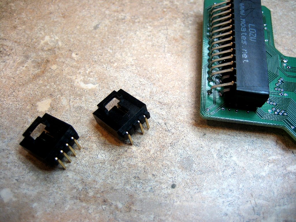
First, look at the connector part you received. It may or may not have had one of the 4 pins removed. If not, pull it out so that it is as shown.
Go ahead and use the no-clean solder that was supplied. Get one spot on the QH connector tinned up like it shows in the picture. 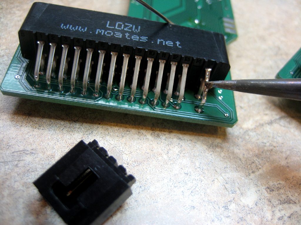
Now, hold the modified 4 (now 3) pin connector in place as shown, re-heating the solder so that the two pieces can be bonded together in the correct position. 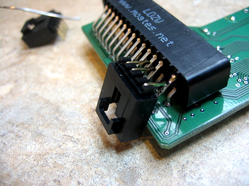

Now, come in with the solder on the other 2 joints. Use a little extra for strength, but don't go overboard. Re-heat and add solder to the first joint you started with here to ensure good connection.
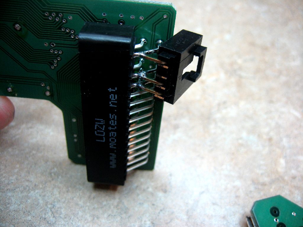
Soldering work is now complete, so check fitment of the cable and look for straightness and orientation. Use the photo below for reference.
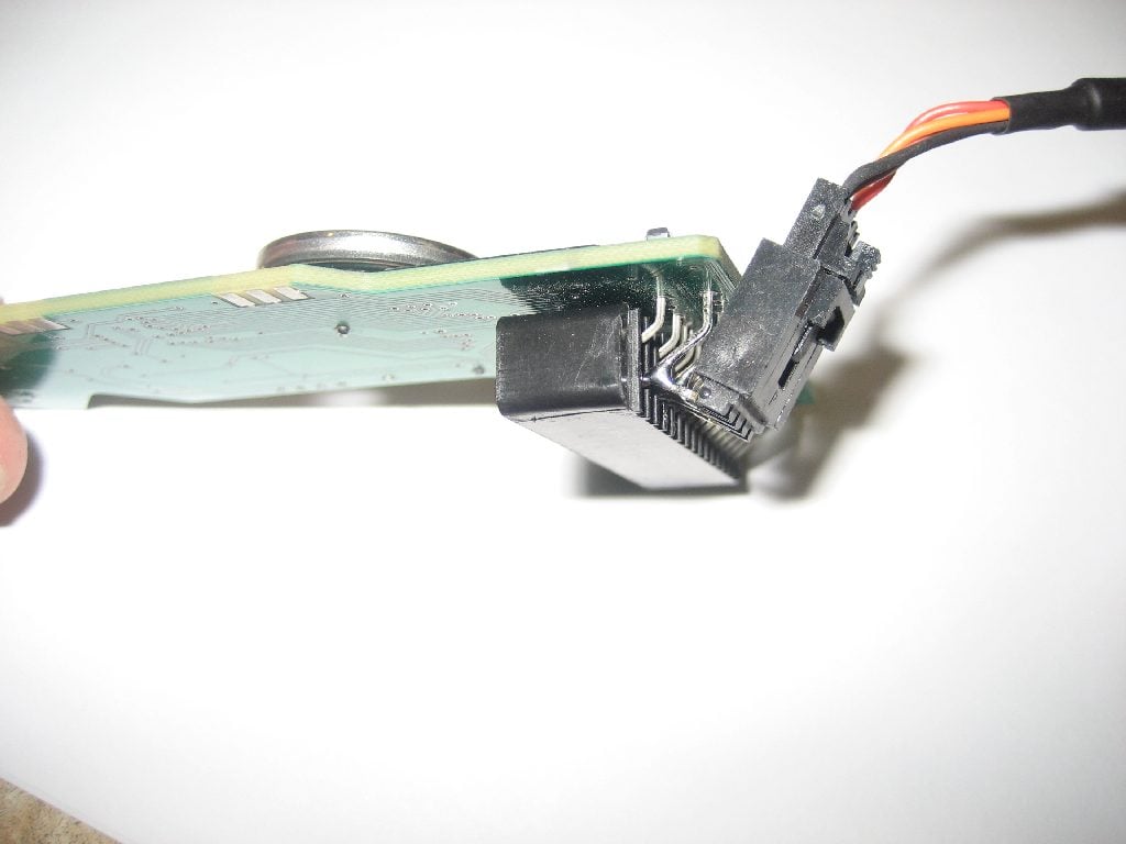
Here's another angle showing solder joint details.

These are most of the parts (pin header shown unmodified) that come with the switch kit. Knob is also included (shown in 2nd picture below).
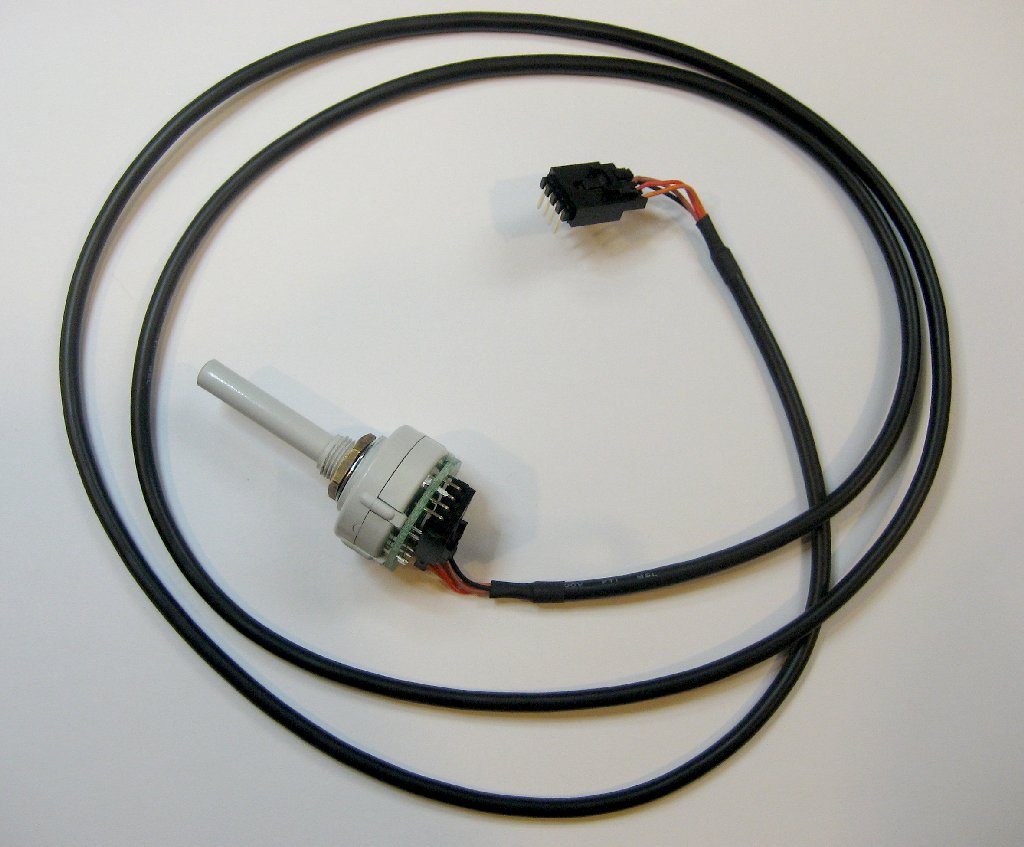
Here is what the completed switch / QH / knob assembly should look like: 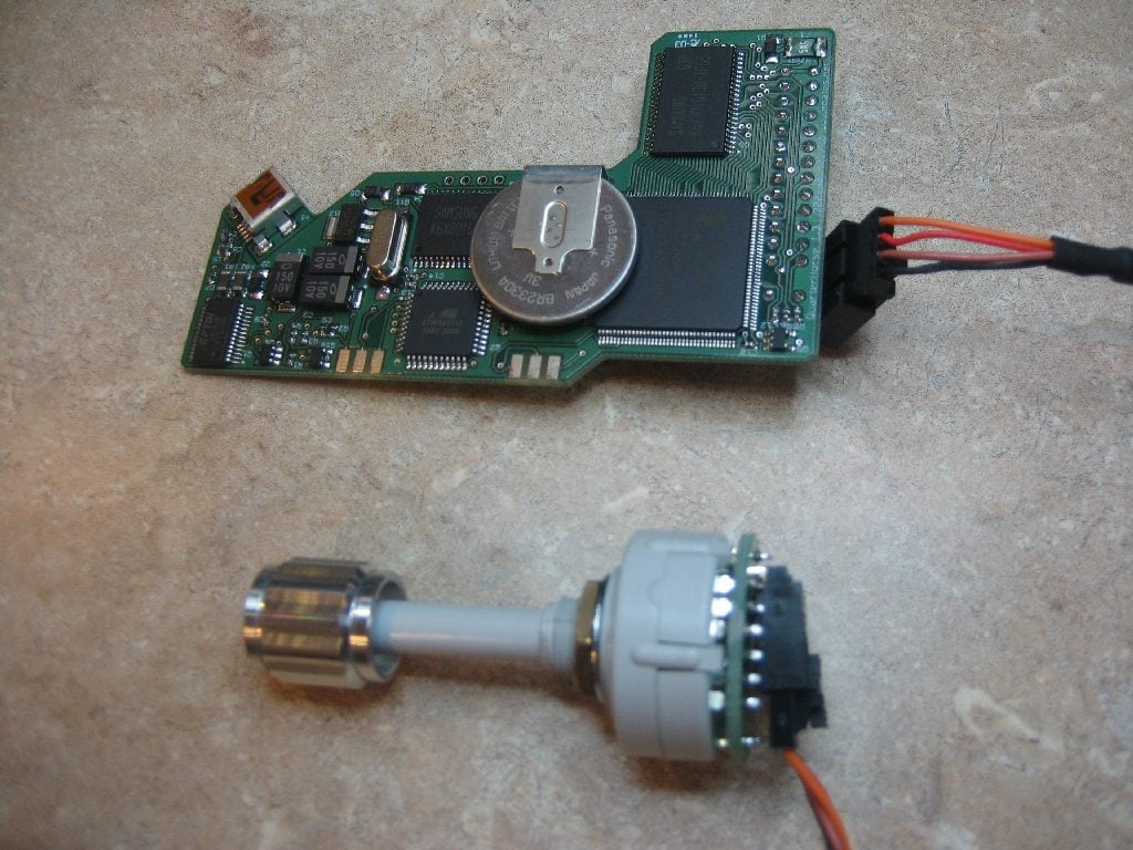
This is a pretty simple installation. It basically overrides the BS0/BS3 lines (if you're familiar with this terminology) at the EEC connector. Therefore, to repeat, this is NOT to be used on EEC-V applications.
Hope this helps! |